中文简体
中文简体 English
 Français
 Deutsch
 عربى
عربى
Content
- 1 What Is 4PPoE?
- 2 A Patch Cord Is Part of the Power Circuit
- 3 1. Conductor Material Affects Power Delivery
- 4 2. Wire Gauge Influences Resistance and Temperature
- 5 3. DC Resistance Balance Matters Across All Four Pairs
- 6 4. Connector Quality Affects Long-Term Reliability
- 7 5. Disconnecting Under Load Can Produce Electrical Arcing
- 8 6. Data Performance Still Matters
- 9 What Should Buyers Look for in a 4PPoE Patch Cord?
- 10 Quality Beyond the Label
Built for Data and Power: Why Patch Cord Quality Matters for 4PPoE
Power over Ethernet has changed the way network devices are installed. By carrying both data and electrical power over the same Ethernet connection, PoE reduces the need for separate power cables, electrical outlets and adapters.
The technology has progressed from IEEE 802.3af and IEEE 802.3at to IEEE 802.3bt, which introduced four-pair power delivery for higher-power applications.
However, upgrading to 4PPoE involves more than selecting a compatible switch and powered device. Every component in the channel—including the patch cords—must carry higher current while maintaining reliable data transmission.
A patch cord may appear to be a small part of the network, but under 4PPoE conditions, its conductor material, wire gauge, termination quality and connector performance can directly affect power delivery, temperature rise and long-term reliability.
What Is 4PPoE?
4PPoE, or four-pair Power over Ethernet, uses all four twisted pairs in an Ethernet cable to transmit power.
Earlier IEEE 802.3af and IEEE 802.3at systems typically delivered power over two pairs. IEEE 802.3bt expanded power delivery to all four pairs and introduced two additional PoE types:
| PoE standard | PoE type | Maximum PSE output | Power available at the PD |
|---|---|---|---|
| IEEE 802.3af | Type 1 | 15.4 W | 13.0 W |
| IEEE 802.3at | Type 2 | 30 W | 25.5 W |
| IEEE 802.3bt | Type 3 | 60 W | 51 W |
| IEEE 802.3bt | Type 4 | 90 W | 71.3 W |
The difference between power supplied by the power sourcing equipment (PSE) and power available to the powered device (PD) accounts for permitted losses within the cabling channel.
IEEE 802.3bt-based equipment uses detection and classification procedures to identify compatible devices and determine how much power should be supplied. The Ethernet Alliance notes that its second-generation PoE certification program is based on Clause 145 of IEEE 802.3, which includes IEEE 802.3bt-2018. Ethernet Alliance PoE Certification Program
Typical 4PPoE applications include:
-
High-performance wireless access points
-
Pan-tilt-zoom IP cameras
-
Video conferencing equipment
-
Digital signage and displays
-
Access control systems
-
Building automation devices
-
LED lighting
-
Thin clients and compatible docking solutions
These applications require both stable data communication and dependable power delivery. That is where patch cord construction becomes especially important.
A Patch Cord Is Part of the Power Circuit
In a conventional data connection, patch cord quality is usually evaluated in terms of bandwidth, insertion loss, return loss and crosstalk.
With 4PPoE, the patch cord also becomes part of the electrical power path.
Current travels through the copper conductors and passes through the contact points between plugs, jacks, patch panels and equipment ports. Resistance at any of these points produces power loss and heat.
The relationship can be expressed as:
Power loss = Current² × Resistance
Because current is squared in this equation, even a relatively small increase in resistance can cause a noticeable increase in heat. Higher conductor resistance, inconsistent contacts or poor termination can therefore affect both the amount of power reaching the device and the operating temperature of the connection.
1. Conductor Material Affects Power Delivery
The conductor is one of the most important differences between a reliable patch cord and a low-cost alternative.
Pure copper conductors offer lower electrical resistance than copper-clad aluminum, commonly known as CCA. Aluminum has significantly higher resistance than copper of the same size, resulting in greater voltage drop and more heat during PoE operation.
Fluke Networks notes that the resistance of a solid aluminum conductor is approximately 55% higher than that of a copper conductor with the same diameter. The additional resistance can lead to increased heating and reduced voltage at the powered device. Fluke Networks: Copper Clad Aluminum Cables
For higher-power PoE applications, selecting patch cords with verified copper conductors is therefore an important starting point.
2. Wire Gauge Influences Resistance and Temperature
Conductor size also affects a patch cord’s ability to carry power.
A larger conductor generally has lower DC resistance and generates less heat than a smaller conductor carrying the same current. This does not mean that every slim patch cord is unsuitable for 4PPoE, but conductor size, cord length, bundle size, ambient temperature and manufacturer specifications must be considered together.
Reduced-diameter patch cords can provide valuable space savings in high-density cabinets. However, they should be specifically designed and verified for the intended PoE application instead of being selected based only on diameter.
This becomes particularly important when many energized cords are tightly bundled. Heat generated by one cord can affect the cords around it, increasing the overall bundle temperature.
Fluke Networks explains that higher cable temperatures increase insertion loss and, under some installation conditions, may require the channel length to be reduced. Larger conductors, suitable temperature ratings and appropriate bundle management can help control this effect. Fluke Networks: Four-Pair PoE and the Cabling Plant
3. DC Resistance Balance Matters Across All Four Pairs
Low total resistance is important, but equal resistance is also essential.
Within each pair, both conductors should have similar resistance so that current is shared evenly. In a four-pair PoE system, resistance should also be appropriately balanced between the powered pair sets.
Excessive DC resistance unbalance can cause current to flow unevenly. This may reduce power-delivery efficiency and, in severe cases, contribute to transformer saturation, distorted Ethernet signals, bit errors or link failure.
The risk can be introduced by:
-
Differences in conductor diameter
-
Inconsistent conductor length
-
Poor crimping
-
Uneven contact pressure
-
Inconsistent termination
-
Variation between cable pairs
Because IEEE 802.3bt uses all four pairs, pair-to-pair resistance balance becomes especially relevant. Fluke Networks’ DSX CableAnalyzer test limits for IEEE 802.3bt include pair-to-pair DC resistance unbalance measurements. Fluke Networks: DC Resistance Unbalance Between Pairs
A basic continuity tester cannot identify these performance problems. It can show whether the conductors are connected, but it cannot verify whether the completed patch cord provides balanced, standards-compliant transmission performance.
4. Connector Quality Affects Long-Term Reliability
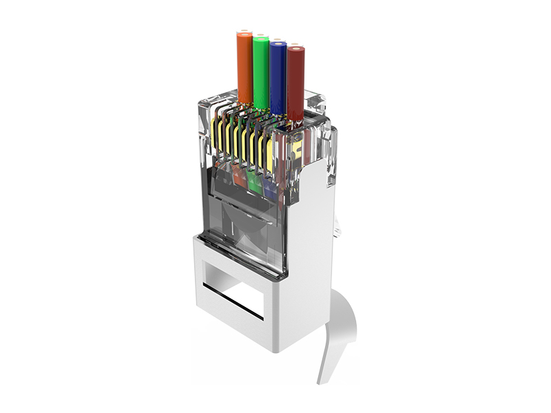
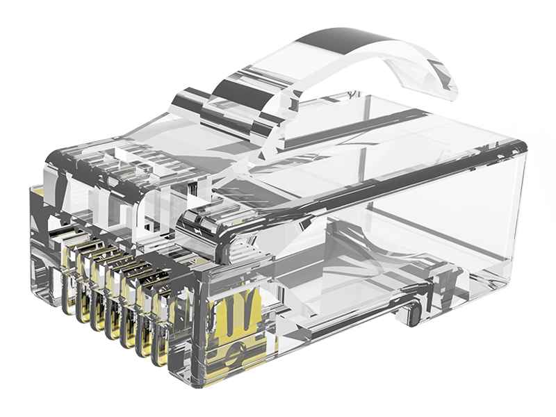
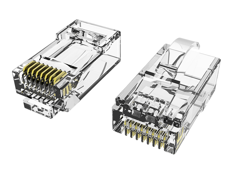
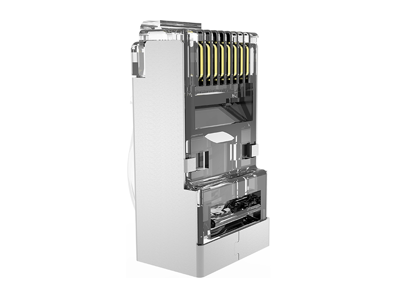
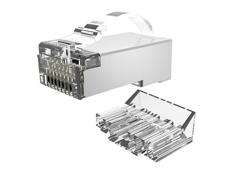
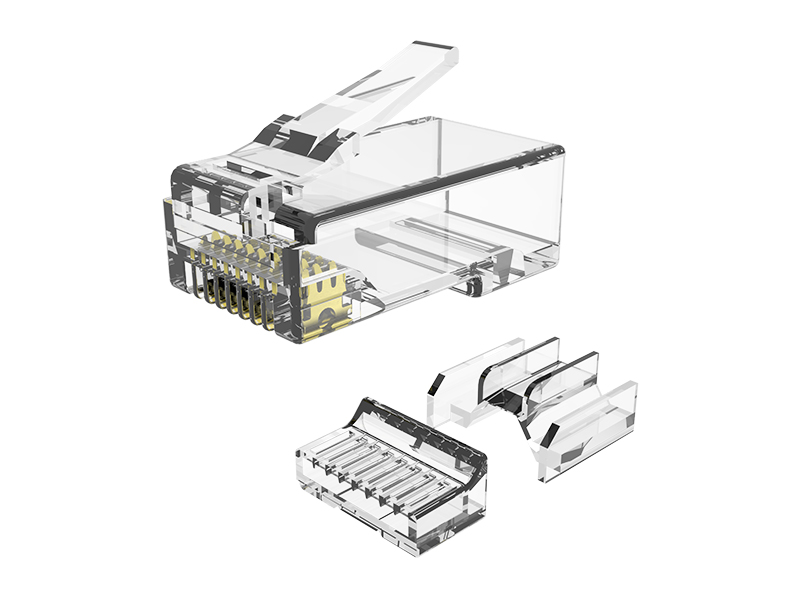
The RJ45 plug is another critical part of the power path.
Stable contact pressure and properly manufactured contacts help keep connection resistance low. Contact material, plating quality, terminal geometry and crimp consistency can all affect long-term performance.
Poor or contaminated contacts may create localized resistance. Under higher current, these points can become areas of additional heat and voltage loss.
Gold plating is often used on the contact surface because it provides corrosion resistance and helps maintain a stable electrical connection. However, a gold-colored contact alone does not confirm quality. Plating thickness, base material, surface consistency and manufacturing control all matter.
The relationship between the conductor and plug terminal is equally important. A reliable termination should create consistent mechanical and electrical contact across all eight conductors.
5. Disconnecting Under Load Can Produce Electrical Arcing
When a PoE connector is unplugged while power is flowing, a small electrical arc may occur as the contacts separate.
Repeated arcing can damage or corrode the contact surface. Over time, this may increase contact resistance and lead to an unreliable connection.
IEC 60512-99-001 and IEC 60512-99-002 provide test procedures for evaluating connectors that are engaged and separated while carrying an electrical load. UL Solutions explains that these tests simulate loaded disconnection and aging conditions to evaluate whether connectors can withstand repeated use. UL Solutions: PoE Connector Testing
For networks in which devices are frequently connected, disconnected or maintained, verified connector durability is particularly valuable.
Whenever possible, PoE power should be disabled before disconnecting equipment. In real installations, however, live disconnection cannot always be avoided, making connector design and testing an important part of system reliability.
6. Data Performance Still Matters
A patch cord built for 4PPoE must carry power without compromising its original purpose: transmitting data.
Higher temperature increases copper resistance and can increase insertion loss. Poor termination may also introduce return loss, crosstalk or other transmission problems.
For this reason, PoE compatibility should not replace category performance testing. A reliable patch cord should be evaluated as a complete cable assembly—not simply checked for continuity or judged by the specification printed on its jacket.
Component-level testing with professional cable certification equipment can help verify parameters such as:
-
Wire map
-
Insertion loss
-
Return loss
-
Near-end crosstalk
-
Propagation delay
-
Delay skew
-
DC loop resistance
-
DC resistance unbalance
The applicable test method and limits should match the patch cord category, construction and intended application.
What Should Buyers Look for in a 4PPoE Patch Cord?
Before selecting patch cords for a higher-power PoE network, consider asking the supplier the following questions:
-
Are the conductors made from pure copper?
-
What conductor gauge and cable construction are used?
-
Is the patch cord specifically suitable for IEEE 802.3bt applications?
-
Has the complete assembly been tested for category transmission performance?
-
Are DC resistance and resistance unbalance controlled?
-
Have the connectors been evaluated for unmating under electrical load?
-
What contact material and plating specification are used?
-
Is the cord suitable for the intended bundle size and operating temperature?
-
Can the supplier provide relevant test reports or certification evidence?
-
Is production quality controlled consistently from batch to batch?
A generic “PoE compatible” description provides limited assurance. Buyers should review the exact power level, installation environment and supporting test evidence.
Quality Beyond the Label
4PPoE creates new possibilities for powering connected devices, but it also places greater electrical and thermal demands on the cabling channel.
The quality of a patch cord can influence:
-
How much power reaches the device
-
How much heat is generated
-
Whether current is shared evenly
-
Whether data transmission remains stable
-
How well the connectors withstand repeated use
-
How reliably the system performs over time
A patch cord designed only to establish a data connection may not be enough for a high-power PoE installation.
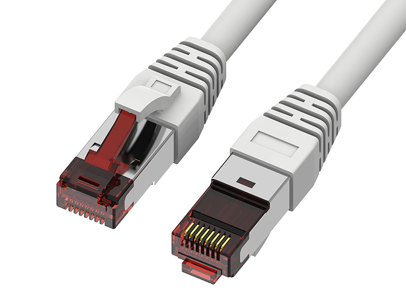
At Ningbo EXW, our patch cords use copper conductors and controlled connector termination. Finished assemblies can be tested with professional Fluke cable certification equipment to verify transmission performance, while 4PPoE-related testing and compliance options are available according to the selected product specification.
When data and power share the same connection, every component matters. Choosing a patch cord designed and verified for both is a small decision that can make a significant difference to the reliability of the entire network.
Looking for patch cords designed for reliable data transmission and 4PPoE applications? Contact Ningbo EXW to discuss your cable category, conductor size, length, connector design and testing requirements.