


 中文简体
 English
 Français
 Deutsch
 عربى
Why Does an RJ45 Plug Fail to Crimp Properly? Common Causes and Solutions
Home / News / Industry News / Why Does an RJ45 Plug Fail to Crimp Properly? Common Causes and Solutions

Content
An RJ45 plug that fails to crimp properly can cause intermittent network connections, failed continuity tests, poor transmission performance, and unnecessary rework.
While crimping may seem like a straightforward process, a reliable RJ45 termination depends on several factors, including cable dimensions, contact design, crimping tool compatibility, and proper wire insertion.
For Ethernet cable manufacturers, installers, and structured cabling suppliers, understanding these factors is essential to reducing termination failures and maintaining consistent product quality.
In this guide, we explore seven common reasons why RJ45 plugs fail during crimping and how to prevent them.
One of the most common causes of RJ45 crimping failure is a mismatch between the modular plug and the Ethernet cable.
Even when two cables are labeled Cat6, their physical dimensions may differ significantly.
Before choosing an RJ45 plug, consider the following specifications:
Conductor Gauge (AWG): The copper conductor size must fall within the plug's supported range.
Insulated Conductor Diameter: The conductor, including its insulation, must fit properly inside the plug's wire channels.
Cable Outer Diameter (OD): The cable jacket must fit the rear opening and strain relief structure.
Conductor Construction: The contact design must be suitable for solid or stranded conductors.
For example, using a plug designed for smaller insulated conductors with a larger Cat6 cable may prevent the wires from reaching their intended positions.
Conversely, an oversized conductor channel may allow excessive movement, increasing the risk of misalignment during crimping.
Solution: Always check the actual cable dimensions against the RJ45 plug specifications rather than relying solely on the cable category.
RJ45 modular plugs commonly use different contact structures, including 2-prong and 3-prong contacts.
These contact designs influence how the metal blades engage the copper conductors during crimping.
Two-prong contacts are commonly used with stranded conductors. Their structure is designed to establish electrical contact with the conductor strands.
Certain three-prong contact designs can accommodate both solid and stranded conductors, depending on their geometry and specifications.
However, not every 3-prong RJ45 plug is automatically compatible with both conductor types.
An unsuitable contact design may result in incomplete conductor penetration, damaged copper strands, or unstable electrical contact.
Solution: Select RJ45 contacts according to the conductor construction and the manufacturer's verified compatibility specifications.
Related reading: 2-Prong vs. 3-Prong RJ45 Plug Contacts: What's the Difference?
The position of the metal contacts inside an RJ45 plug is another important factor affecting crimping quality.
If the contacts are positioned incorrectly before termination, several problems may occur:
Contacts may shift or become tilted during crimping.
The crimping tool may not engage the contacts correctly.
Contacts may fail to penetrate the conductor insulation sufficiently.
Uneven contact heights may affect mating reliability.
Excessive or insufficient pre-insertion depth can also contribute to assembly difficulties.
Solution: Use RJ45 plugs manufactured with controlled contact positioning and consistent assembly tolerances. After crimping, inspect the contacts for alignment and proper engagement.
Not all RJ45 crimping tools are suitable for every modular plug design.
Standard RJ45 plugs, pass-through connectors, shielded plugs, and larger-diameter plugs may require different crimping mechanisms or compatible dies.
Using an unsuitable tool can lead to:
Incomplete contact compression
Uneven contact heights
Housing deformation or cracking
Improper strain relief compression
Incomplete wire trimming on pass-through plugs
Worn or damaged crimping tools can also affect termination consistency.
Solution: Use a crimping tool approved for the specific RJ45 plug design. Inspect and maintain the tool regularly, particularly when performing high-volume cable assembly.
Even when the plug and cable are compatible, incorrect wire insertion can cause termination failure.
Common mistakes include incorrect T568A/T568B wire arrangement, uneven wire lengths, conductors that do not reach the front of the plug, and excessive untwisting of cable pairs.
If a conductor is not fully inserted, the metal contact may fail to establish a reliable electrical connection.
Excessive pair untwisting can also negatively affect high-frequency transmission performance, particularly in Cat6 and Cat6A applications.
Solution: Verify the wire sequence, trim conductors evenly, and ensure all eight conductors are fully seated before crimping. Maintain the pair twists as close to the termination point as the connector design allows.
The strain relief structure helps secure the cable jacket inside the RJ45 plug.
If the cable outer diameter is too small for the plug's strain relief design, the cable may move or pull out under mechanical stress.
If the jacket is too large, it may not enter the plug correctly, preventing proper crimping.
Inadequate strain relief can transfer pulling forces directly to the terminated conductors, potentially causing intermittent connections.
Solution: Match the cable jacket diameter to the plug's specified range and ensure the strain relief properly grips the jacket without damaging the internal conductors.
Not every crimping failure originates from the cable or installation process.
Variations in RJ45 plug manufacturing can also affect termination quality.
Potential issues include:
Inconsistent contact dimensions or positioning
Deformed plastic housings
Irregular conductor channels
Poorly assembled metal contacts
Dimensional variations between production batches
These problems can increase termination difficulty, especially in automated or high-volume patch cord production.
Solution: Choose an RJ45 plug manufacturer with controlled tooling, contact stamping, molding, assembly, and inspection processes.
Consistent component dimensions help support more predictable crimping results.
|
Common problem |
Possible cause |
Recommended solution |
|---|---|---|
|
Wires cannot enter the plug |
Insulated conductor diameter too large |
Select a compatible conductor-hole size |
|
Contacts do not crimp evenly |
Incorrect tool or contact positioning |
Check crimping die and contact alignment |
|
Cable pulls out easily |
Cable OD and strain relief mismatch |
Choose the correct rear-entry design |
|
Continuity test fails |
Incomplete wire insertion or contact engagement |
Inspect wire seating and contact penetration |
|
Plug housing cracks |
Excessive crimping force or incompatible tooling |
Verify tool and plug compatibility |
|
Network performance fails |
Excessive untwisting or termination inconsistency |
Review wire preparation and perform appropriate testing |
A reliable RJ45 termination begins before the crimping process.
For manufacturers and installers, the following practices can help improve consistency:
Verify the cable AWG, insulated conductor diameter, and overall cable OD.
Select the correct contact structure for solid or stranded conductors.
Confirm compatibility between the RJ45 plug and crimping tool.
Inspect wire insertion and contact alignment before crimping.
Perform visual inspections and continuity testing after termination.
Conduct additional mechanical and transmission performance testing where required.
For production applications, sample termination trials using the actual cable and tooling can help identify compatibility problems before mass production.
At Ningbo EXW, we understand that reliable RJ45 termination requires more than a connector that simply fits the cable.
With over 40 years of experience through the EXW group, we manufacture RJ45 modular plugs and Ethernet patch cords for a wide range of structured cabling applications.
Our manufacturing capabilities include precision stamping, electroplating, injection molding, automated contact insertion, and connector assembly.
We offer various RJ45 modular plug designs, including different contact structures, conductor compatibility options, and gold plating thicknesses to meet different application requirements.
Our engineering and tooling teams support connector selection and product customization for OEM and ODM customers.
Whether you are manufacturing Ethernet patch cords or selecting modular plugs for your cable products, choosing the correct plug design can help reduce crimping failures and improve production consistency.
Q1: Why do my RJ45 connectors fail continuity tests after crimping?
Common causes include incorrect wire arrangement, incomplete conductor insertion, unsuitable contact geometry, or insufficient contact engagement. Inspect the termination and verify cable-to-plug compatibility.
Q2: Can I use the same RJ45 plug for solid and stranded Ethernet cables?
Some RJ45 plugs are designed for both solid and stranded conductors, while others support only one type. Always confirm the manufacturer's compatibility specifications.
Q3: Why does my RJ45 plug crack during crimping?
Housing cracking may result from incompatible crimping tools, excessive mechanical pressure, plug misalignment, or material and dimensional issues.
Q4: Does gold plating thickness affect RJ45 crimping quality?
Gold plating thickness primarily relates to the durability and reliability of the mating contact surface. It does not directly determine whether a plug can be crimped correctly. Contact geometry, material properties, and termination conditions are more relevant to the crimping process.
Q5: Can an RJ45 cable pass a continuity test but still have performance problems?
Yes. A continuity test checks basic electrical connections, but it does not verify all transmission characteristics. Additional testing may be required to evaluate parameters such as NEXT and return loss.
RJ45 crimping failures are often caused by a combination of cable incompatibility, unsuitable contact design, incorrect tool selection, and inconsistent termination practices.
Selecting the right RJ45 modular plug for the cable's actual dimensions and conductor construction is one of the most effective ways to prevent these problems.
Looking for RJ45 plugs that match your cable specifications?
Contact Ningbo EXW to discuss your cable AWG, insulated conductor diameter, cable outer diameter, and termination requirements. Our team can help you identify suitable RJ45 modular plug options for your application.
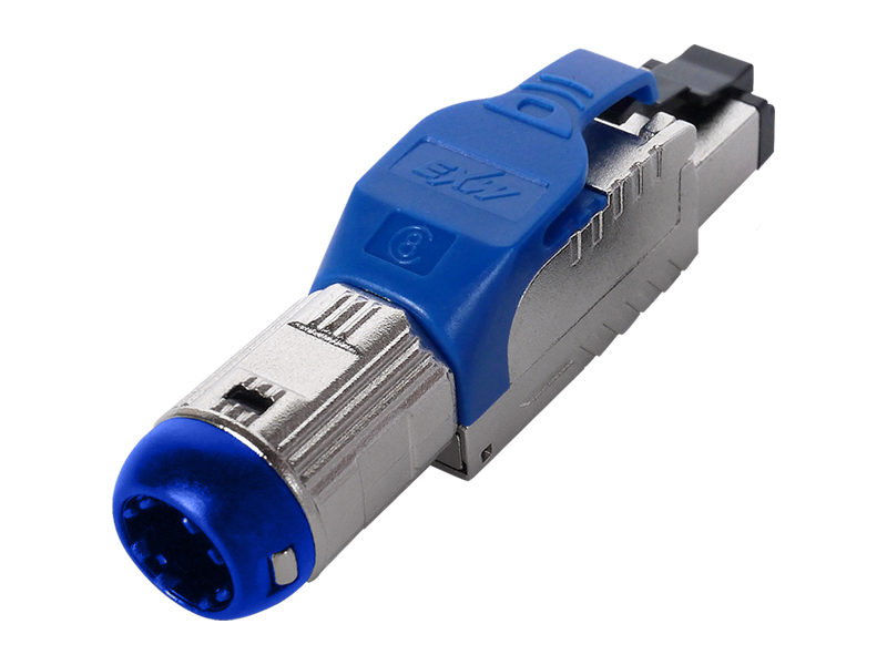
Cat.8 Field Termination Plug | GHMT Certified RJ45 Connector for 40G Ethernet Cabling
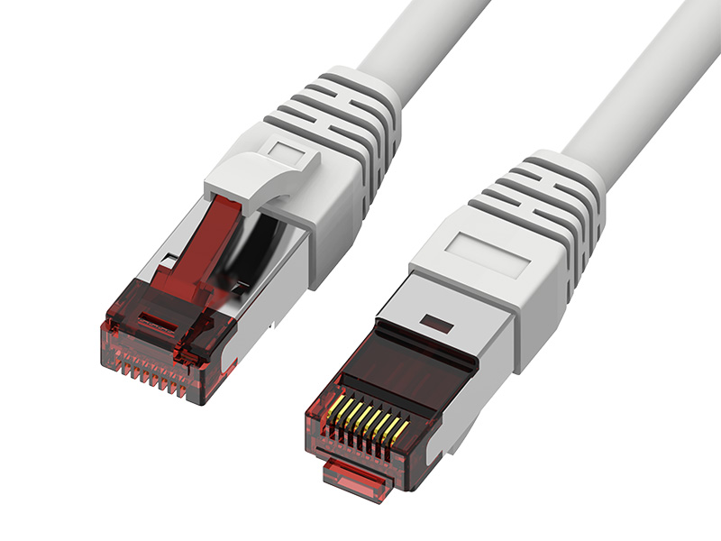
Cat.6A S/FTP Patch Cord | Fluke Tested 10G Shielded RJ45 Ethernet Cable
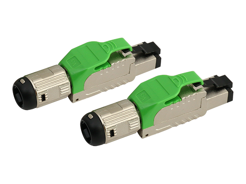
Cat.6A Field Termination Plug | Shielded RJ45 Connector for 10G Ethernet & 4PPoE Cabling
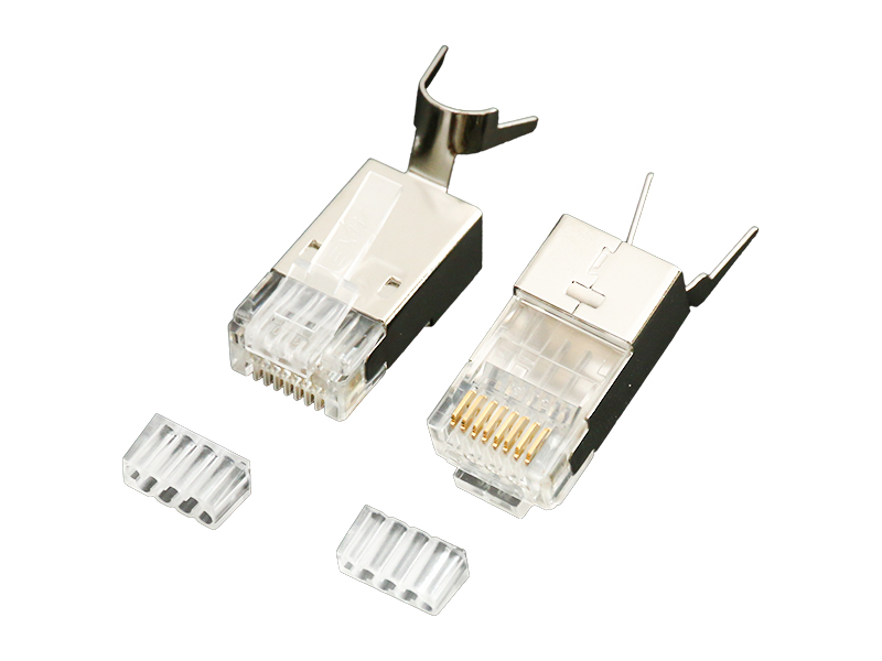
Fat OD Modular Plug | RJ45 Connector for Large Diameter Ethernet Cable Applications
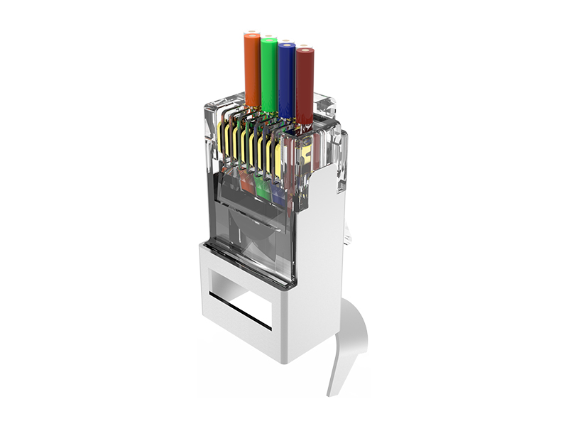
Fat OD Pass-Through Plug | RJ45 Connector for Large Diameter Ethernet Cable Applications
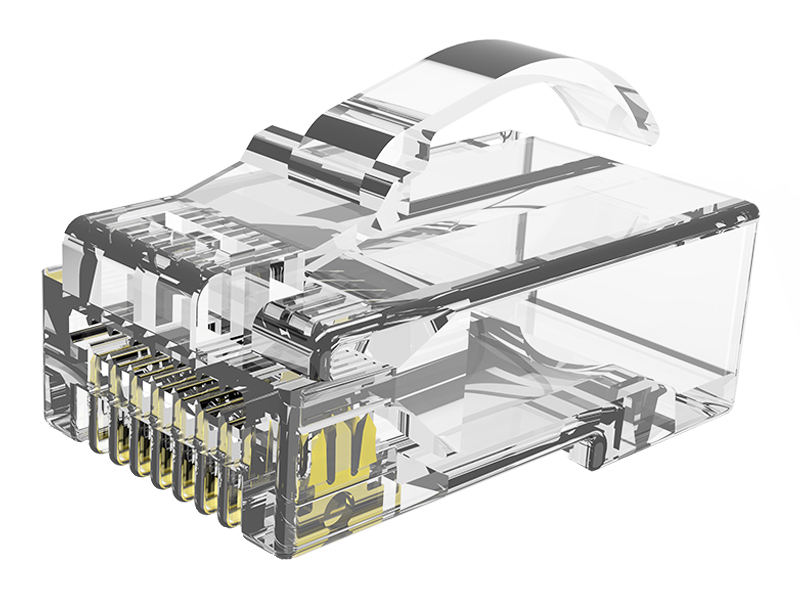
Cat.5E UTP Arch Latch Modular Plug | RJ45 8P8C Connector for Ethernet Cabling
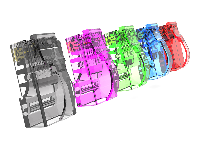
Cat.5E STP Arch Latch Modular Plug | Shielded RJ45 8P8C Connector for Ethernet Cabling
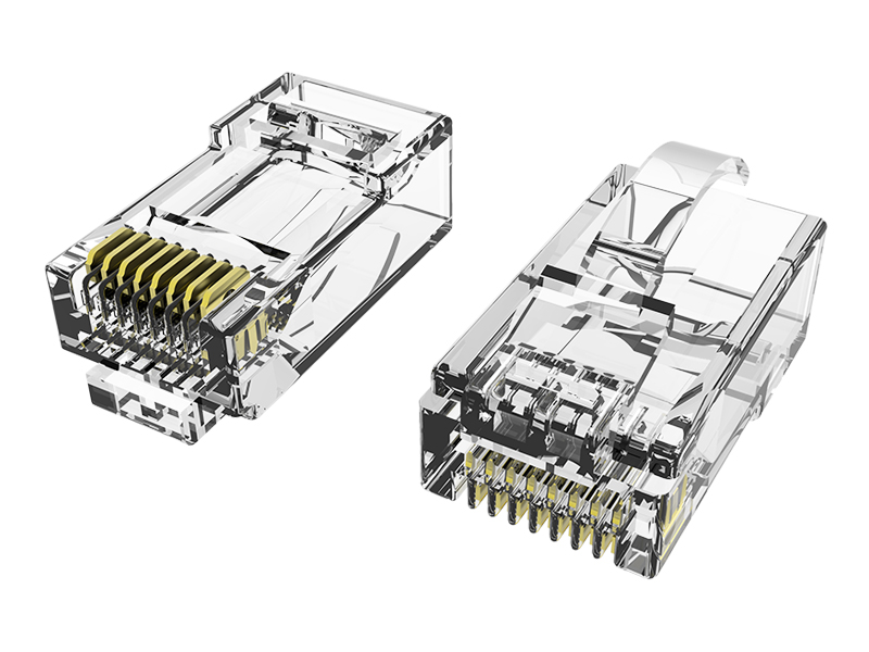
Cat.6 UTP Arch Latch Modular Plug | RJ45 8P8C Connector for Ethernet Cabling
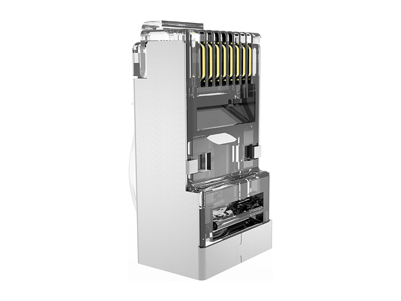
Cat.6 STP Arch Latch Modular Plug | Shielded RJ45 8P8C Connector for Ethernet Cabling
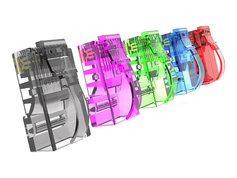
Cat.6A UTP Arch Latch Modular Plug | RJ45 8P8C Connector for 10G Ethernet Cabling
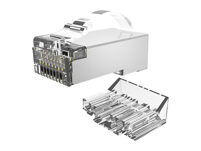
Cat.6A STP Arch Latch Connector | Shielded RJ45 8P8C Connector for 10G Ethernet Cabling
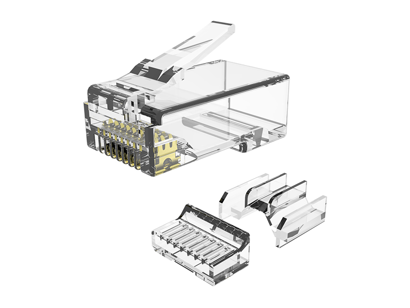
Cat.6A UTP 3R Modular Plug | RJ45 8P8C Connector for 10G Ethernet Cabling

 No. 651, Hengshanxi Road, Beilun, Ningbo, Zhejiang Province, China
 sales@nbexw.com
 +86-574-86868738
 +86 138 5828 0875