中文简体
中文简体 English
 Français
 Deutsch
 عربى
عربى
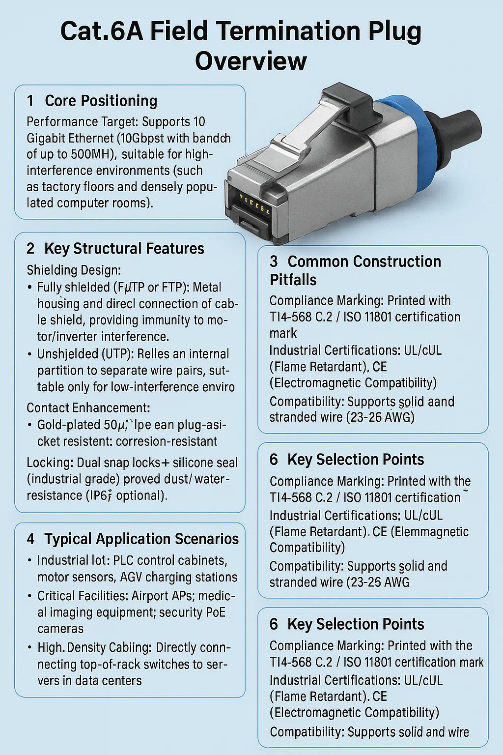
Cat.6A Field Termination Plug Overview
1. Core Positioning
Performance Target: Supports 10 Gigabit Ethernet (10Gbps) with a bandwidth of up to 500MHz, suitable for high-interference environments (such as factory floors and densely populated computer rooms).
Differentiating from Traditional Connectors: Built-in crosstalk compensation circuitry (PCB or metal partition) solves the signal crosstalk issue with standard RJ45 plugs at 10Gbps.
2. Key Structural Features
Shielding Design:
Fully shielded (F/UTP or FTP): Metal housing and direct connection of cable shield, providing immunity to motor/inverter interference.
Unshielded (UTP): Relies on an internal partition to separate wire pairs, suitable only for low-interference environments. Contact Enhancement:
Gold-plated 50μ" pins are plug-and-socket resistant, corrosion-resistant, and support high-current PoE++ (90W).
Locking:
Dual snap locks + silicone seal (industrial grade) prevent vibration and fallout, and are dust/water-resistant (IP67 optional).
3. Construction-Specific Requirements
Cable Handling:
When stripping the cable sheath, leave the aluminum foil layer on the wire pairs (shielded models) intact. Do not cut the insulation.
Maintain a twist length of less than 13mm to avoid excessive crosstalk caused by untwisting.
Termination:
IDC crimp terminals (not crimping). Press down vertically to ensure insulation penetration.
The shield must maintain 360° contact with the metal housing. "Pigtail" grounding is prohibited.
4. Typical Application Scenarios
Industrial IoT: PLC control cabinets, motor sensors, AGV charging stations.
Critical Facilities: Airport APs, medical imaging equipment, security PoE cameras.
High-Density Cabling: Directly connecting top-of-rack switches to servers in data centers.
5. Common Construction Pitfalls
Mistake 1: Using unshielded plugs with shielded cable → Grounding failure, EMI intrusion.
Misconception 2: Wire pairs not inserted in color-coded order → Near-end crosstalk (NEXT) increases dramatically.
Misconception 3: Neglecting to tighten the housing → Ports loosen and lose power in vibrating environments.
6. Key Selection Points
Compliance Marking: Printed with the TIA-568-C.2 / ISO 11801 certification mark.
Industrial Certifications: UL/cUL (Flame Retardant), CE (Electromagnetic Compatibility).
Compatibility: Supports solid and stranded wire (23-26 AWG).
7. Differences from Standard Category 6 Plugs
| Feature | Cat.6A Field Termination Plug | Standard Cat.6 Crimp Plug | Practical Impact |
| 10Gbps Stability | Supports full 100m runs at 10Gbps(Uses internal crosstalk-compensating circuits). | Limited to ≤37m for 10Gbps;No signal compensation. | Cat.6A enables future-proof 10G deployments; Cat.6 crimps restrict topology flexibility. |
| Interference Resistance | Optional full metal shielding(FTP/SFTP compatibility). | Unshielded design;Vulnerable to EMI/RFI. | Critical for factories/medical use; Cat.6 fails near motors or HV equipment. |
| PoE Support | Arcing-resistant contactsHandles 90W PoE++ without degradation. | Risk of plastic meltingwith sustained >60W loads. | Safe for high-power IoT/APs; Cat.6 crimps risk fire in PoE++ scenarios. |
| Termination Method | Punch-down (IDC) termination;Allows re-termination if errors occur. | Crimp-only;Errors require cutting and restarting. | Field plugs reduce waste and troubleshooting time; crimps increase installation costs. |
| Standards Compliance | Exceeds TIA-568.2-D requirementsfor permanent 10G links. | Meets basic patch cord standards(TIA short-channel). | Guarantees certification testing passes; crimps often fail alien crosstalk tests. |