中文简体
中文简体 English
 Français
 Deutsch
 عربى
عربى
1. Tools & Materials Required
Field termination plug (RJ45, M12, or other type).
Cable stripper (for precise jacket removal).
Punch-down tool (for IDC termination).
Cable tester (to verify continuity & performance).
Scissors or flush cutters (for trimming wires).
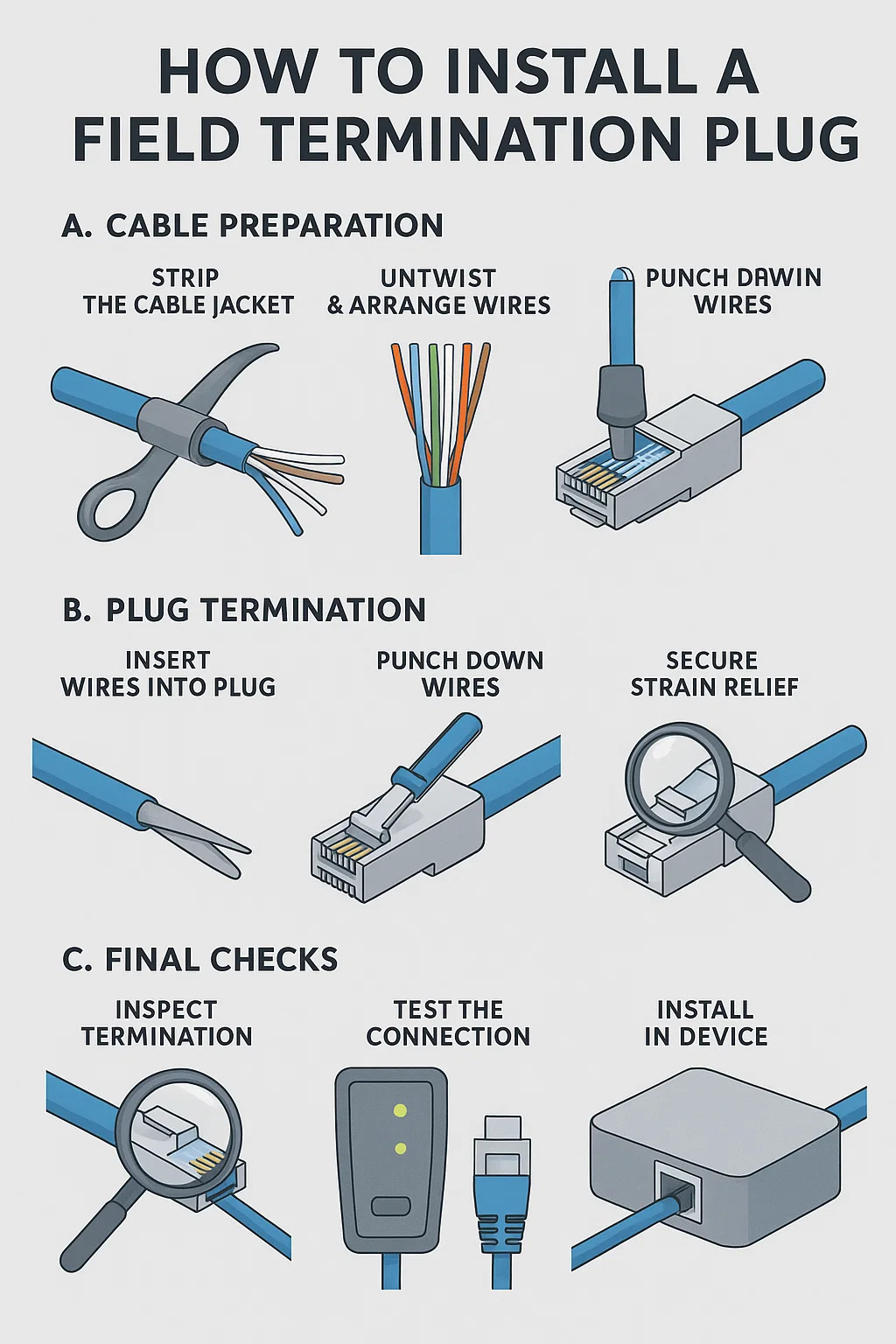
2. Step-by-Step Installation
A. Cable Preparation
--Strip the Cable Jacket
Use a stripper to remove 1-1.5 inches of the outer jacket.
Avoid nicking inner conductors.
--Untwist & Arrange Wires
Follow the plug's color code (T568A or T568B).
Keep twists intact up to the termination point.
--Trim Wires to Length
Cut wires evenly, leaving 0.25-0.5 inches exposed.
B. Plug Termination
--Insert Wires into Plug
Align conductors with the plug's IDC slots.
Ensure no crossed or loose wires.
--Punch Down Wires
Use a punch-down tool to seat wires firmly.
Apply even pressure to avoid partial connections.
--Secure Strain Relief
Clamp the cable jacket inside the plug to prevent pullout.
C. Final Checks
--Inspect Termination
Verify no stray wire strands or misaligned contacts.
--Test the Connection
Use a cable certifier (for high-speed networks) or continuity tester.
--Install in Device
Plug into the target device (IP camera, AP, etc.) and confirm functionality.
3. Common Mistakes to Avoid
Over-trimming wires → Poor contact.
Incorrect wire order → Signal failure.
Skipping strain relief → Cable damage over time.
Not testing after install → Hidden faults.
4. When to Re-Terminate
If testing fails (open/short circuits).
If the plug feels loose or unstable.
If corrosion or damage is visible.
| Step | Action | Critical Details | Tool/Check |
| 1. Strip Cable | Remove 1–1.5 inches of outer jacket without damaging inner conductors. | Avoid cutting into wire insulation; preserve twists near jacket end. | Cable stripper + visual inspection. |
| 2. Arrange Wires | Untwist and align wires to T568A/B scheme. | Maintain twists up to IDC slots; no crossed pairs. | Follow plug’s color guide (printed or molded). |
| 3. Trim Wires | Cut wires to 0.25–0.5 inches exposed. | Ensure uniform length; no frayed ends. | Flush cutters (scissors risk uneven cuts). |
| 4. Insert into Plug | Seat wires into plug’s IDC slots until fully seated. | Wires must reach terminal bottoms; no gaps or misalignment. | Magnifying glass (verify seating under poor lighting). |
| 5. Punch Down | Terminate wires with punch-down tool at 45° angle. | Single firm press per wire; avoid partial punches or over-compression. | Impact punch-down tool (non-impact may require multiple strikes). |
| 6. Secure Strain Relief | Clamp cable jacket inside plug body. | Jacket must be gripped tightly; no exposed wires outside plug. | Tug test: gentle pull to confirm strain relief holds. |
| 7. Test Connection | Verify continuity, wire map, and (if applicable) PoE/signal stability. | Check for opens/shorts; validate impedance for high-speed links. | Cable certifier (e.g., Fluke) or basic tester for pass/fail. |
| 8. Install in Device | Connect to endpoint (camera, AP, etc.) and confirm operation. | Ensure plug locks securely; no intermittent disconnects. | Functional test (e.g., ping, video feed, PoE power check). |